Plant Engineering Process Piping BIM:
3D Model Verification & Coordination
Detailed engineering review, P&ID interpretation, 3D pipe routing verification, and interdisciplinary Navisworks clash resolution for critical BFS process lines. Designed to guarantee strict fidelity between engineering documentation and 3D plant spatial coordination.
1. Executive Summary
This case study details our specialized engineering deliverables for a major Plant Engineering process-piping BIM project. The primary objective was to thoroughly analyze incoming engineering inputs, systematically verify received 3D plant models against authoritative Piping & Instrumentation Diagrams (P&IDs), identify critical modeling discrepancies, develop fully coordinated process piping routes, and deliver an accurate, clash-free BIM model to the project team.
The core focus of this project centered on P&ID interpretation, spatial pipe routing, valve and instrument placement accuracy, nozzle connection checks, and multi-disciplinary clash detection.
Project Profile REF: CS-BIM-024
- Project Type
- Plant Engineering / Process Piping
- Discipline
- Process Piping BIM
- Primary BIM Platform
- Autodesk Revit
- Coordination / Clash
- Autodesk Navisworks
- 2D Drafting Reference
- Autodesk AutoCAD
- Main Engineering Input
- P&ID Specifications
- Focus Lines
- BFS Piping – Line 24 & 25
2. Scope of Work & BIM Specialist Role
In industrial plant engineering, 3D BIM models cannot be created in isolation. Our role required extensive engineering interpretation, acting as the bridge between 2D P&ID intent and 3D spatial reality.
📋 Defined Project Scope
- ✓ Review and understand all process P&ID engineering inputs.
- ✓ Identify line numbers, pipe sizes, specs, flow directions, and equipment connections.
- ✓ Verify available received 3D model against engineering data.
- ✓ Pinpoint missing, incorrect, or inconsistent piping components.
- ✓ Model or modify process lines directly within Autodesk Revit.
- ✓ Coordinate routing, pipe elevations, and valve accessibility.
- ✓ Perform interdisciplinary Navisworks clash detection & resolution.
⚙️ Key Technical Responsibilities
- ▸ Reading and interpreting complex industrial P&IDs.
- ▸ Tracking process line numbers (Line 24 & 25) and component logic.
- ▸ Checking equipment nozzle locations, ratings, and pipe connections.
- ▸ Placing exact inline components: elbows, tees, reducers, strainers, and valves.
- ▸ Maintaining proper maintenance clearances around valve actuators and gauges.
- ▸ Documenting discrepancies and issuing engineering clarification requests.
- ▸ Iterative Navisworks clash matrix auditing and resolution re-checks.
3. P&ID to 3D BIM Workflow Pipeline
Click through the interactive stages below to explore our systematic engineering-to-modeling process, ensuring complete fidelity between schematic diagrams and 3D plant layout.
4. Engineering Model Verification & Discrepancy Breakdown
Received 3D models frequently omit critical inline components specified on engineering P&IDs. Our rigorous cross-checking ensures every valve, branch, instrument, and reducer is accurately placed.
Practical Discrepancy Example: BFS Line Instrument Branch
Toggle views below to compare the source P&ID requirement versus initial & final 3D states.
5. Navisworks Clash Resolution
Process piping operating within tight industrial envelopes must be strictly coordinated with structural framing, electrical cable trays, HVAC ducting, and equipment access zones.
Using Autodesk Navisworks, we executed multi-disciplinary clash tests, identified physical and clearance conflicts early, and adjusted pipe routes, elevations, and offsets in Revit prior to fabrication.
Clash Detection Resolution Summary by Discipline
Data represents initial conflicts detected vs. resolved state in final model.
6. 3D Model Visual Renders (Before vs. After)
Side-by-side visual documentation comparing the initial unverified 3D model against our completed, coordinated, and P&ID-verified process piping model in Autodesk Revit.
Figure 1: BFS Line 24 Actuator & Bypass Valve Assembly
Lines 24/25 Header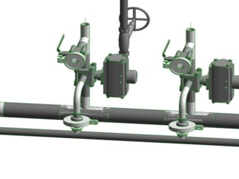
URL:
src="" (Add Image URL Here)Dimensions: ~800x600px | Format: PNG/JPG
Shows initial line layout lacking actuator control branches and flexible routing.
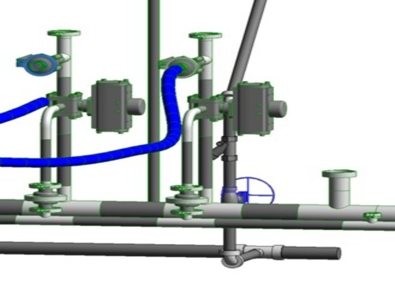
URL:
src="" (Add Image URL Here)Dimensions: ~800x600px | Format: PNG/JPG
Shows fully modeled pneumatic actuator valves, blue flexible hose loops, and correct flanges.
Figure 2: Pressure Gauge & Reducer Fitting Loop
Instrumentation Station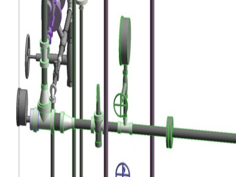
URL:
src="" (Add Image URL Here)Dimensions: ~800x600px | Format: PNG/JPG
Initial 3D route showing single inline reducer without downstream instrument tap.
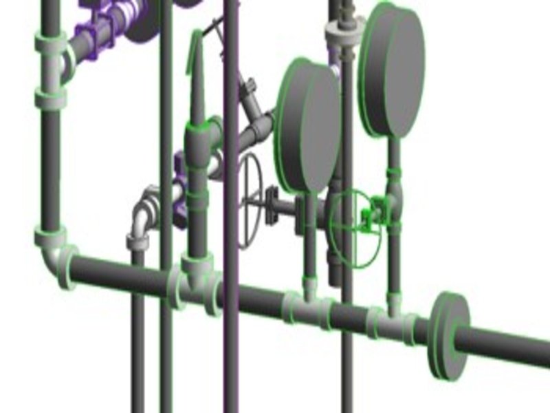
URL:
src="" (Add Image URL Here)Dimensions: ~800x600px | Format: PNG/JPG
Fully detailed instrumentation branch featuring dual pressure gauges, root valves, and fittings.
Figure 3: Pressure Regulator & Y-Strainer Line Arrangement
Line 25 Low-Pressure Loop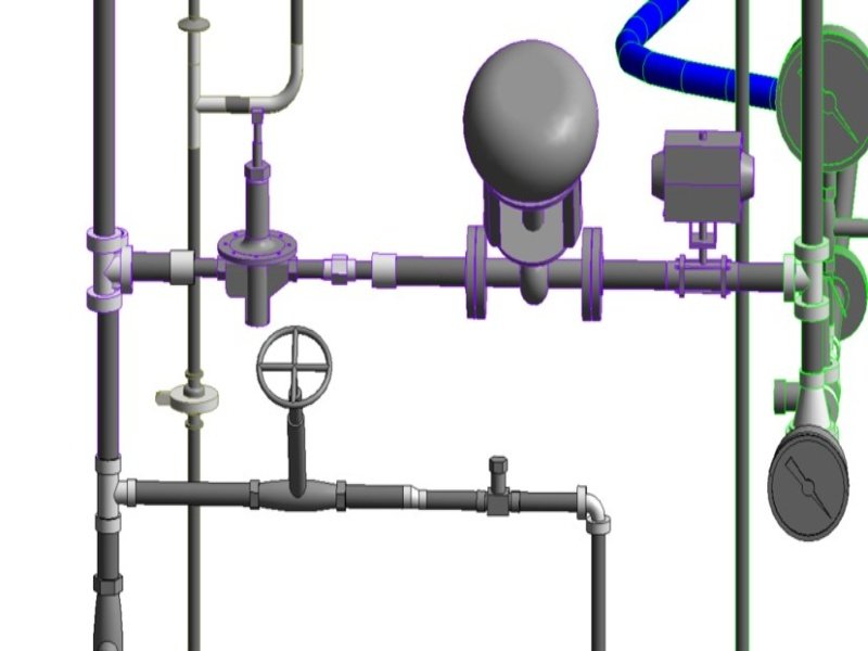
URL:
src="" (Add Image URL Here)Dimensions: ~800x600px | Format: PNG/JPG
Incomplete modeling showing diaphragm regulator without inline Y-strainer or bottom drain valve.
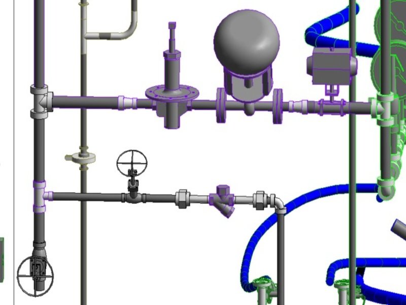
URL:
src="" (Add Image URL Here)Dimensions: ~800x600px | Format: PNG/JPG
Accurately modeled Y-strainer assembly, bottom isolation valve handwheel, and connected flexible lines.
7. Model Quality Control & Audit Checklist
Interactive validation protocol applied to every process line prior to final model release.
⚠️ Key Challenges Encountered
- P&ID vs. 3D Model Mismatches: Systematically audited line numbers rather than assuming received models were correct.
- Missing Inline Components: Replaced missing valves, strainers, and instruments using precise manufacturer parameters.
- Interdisciplinary Interference: Re-routed congested pipe runs around structural columns and primary electrical tray runs.
🛠️ Tools & Software Stack
3D process piping BIM modeling, pipe specs, routing, and family creation.
3D multi-disciplinary model aggregation, clash detection matrix, and review.
2D P&ID schematic reference review, symbol checking, and line drafting verification.
🎓 Skills & Competencies
Delivering Engineering Accuracy & Spatial Integrity
The primary outcome was a reliable, fully coordinated process-piping BIM model based on systematic engineering verification. By bridging the gap between schematic P&IDs and 3D Revit models, we eliminated costly field clashes and guaranteed that the final digital asset reflected 100% engineering intent.