- Analyzing the Existing Sheet Metal Design
Begin with a thorough analysis of the existing sheet metal design. Key factors to assess include:
- Geometry and Constraints: Identify the geometry of the current part, including bends, folds, holes, and attachment points.
- Structural Requirements: Evaluate the component’s load-bearing capacity, durability needs, and potential stress points.
- Functionality and Assembly Fit: Note how the part interacts with surrounding components and whether a design change could affect assembly fit and
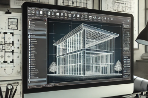
CAD tools such as SolidWorks or AutoCAD can be used to create detailed 3D models of the original sheet metal part, facilitating a clear understanding of these requirements.
2. Selecting the Right Aluminum Alloy
Choosing the appropriate aluminum alloy is crucial since not all aluminum grades are suitable for extrusion or have the same mechanical properties. Commonly used automotive-grade alloys include:
- 6061-T6: Offers a good balance of strength, weldability, and corrosion
- 6063: Known for its excellent finish and suitability for intricate
- 7005: High strength and used in structural components that demand greater load- bearing capacity.
CAD-integrated materials databases, like those in SolidWorks, Inventor, or Fusion 360, allow designers to select the correct alloy and visualize its properties in the digital model.
3. Redesigning for Extrusion
With aluminum extrusion, it’s possible to design complex cross-sectional shapes not feasible with sheet metal. Key redesign steps include:
- Simplifying Geometry: Consider transitioning folds, bends, and complex geometries to straight sections that match the extrusion die’s profile.
- Reducing Part Count: Combine parts when possible by redesigning them as a single extrusion, reducing the need for assembly and fasteners.
- Optimizing Wall Thickness: Adjust wall thickness for weight reduction without compromising CAD tools like Fusion 360 offer stress analysis simulations that can help determine optimal thickness based on load-bearing requirements.
4. Adding Necessary Features for Assembly and Attachment
Extruded aluminum designs often require post-extrusion machining to add holes, slots, or cutouts for assembly. Use CAD to model these features and ensure precise integration.
SolidWorks’ Hole Wizard and Feature Toolkits are useful for adding complex features like:
- Attachment Points: Add slots, tabs, or holes for bolting, riveting, or
- Interlocking Shapes: Design tongues and grooves for ease of assembly and secure fitment.
Simulations can further verify that these features won’t impact the part’s structural integrity.
5. Evaluating Structural Performance through Simulation
Once the design is complete, use CAD-integrated Finite Element Analysis (FEA) tools to evaluate the structural integrity of the new extrusion model. These simulations can reveal potential weak points, stress concentrations, and deformation risks under various loading conditions.
Key tools include:
- SolidWorks Simulation: Allows for linear and non-linear FEA on different
- ANSYS: Offers extensive structural analysis capabilities, including thermal and fatigue analysis.
With FEA, you can validate that the extrusion meets automotive safety and durability standards before moving to physical prototyping.
6. Cost Analysis and Tooling Setup
As extrusion tooling can be expensive, use your CAD design to estimate costs and check the design’s feasibility for mass production. Key steps include:
- Die Design & Costing: CAD tools like AutoCAD or SolidWorks can help design the extrusion
- Material Efficiency: Evaluate material yield to ensure minimum waste in
Some CAD tools have modules that integrate with costing software, allowing you to estimate production costs based on design parameters, alloy choice, and tooling complexity.